5G defines three application scenarios: enhanced Mobile Broadband (eMBB), Massive Machine-Type Communications (mMTC), and ultra-reliable low-latency communication (URLLC).
URLLC delivers communications with ultra-low latency and ultra-high reliability, and can meet network requirements of some latency-sensitive, reliability-stringent services, such as autonomous driving, smart manufacturing, remote diagnostics, augmented reality (AR)/virtual reality (VR), and high-definition (HD) videos. URLLC is involved in end-to-end (E2E) transmission procedures across the core network, transport network, and RAN.
Moreover, multiple network deployment solutions are available to suit different industries and applications.
The URLLC technologies applied on the RAN side and typical network deployment solutions will be discussed.
3GPP TS 22.261 defines the requirements of different services for communication latency and reliability on the RAN side. Table 2-1 illustrates such requirements of some services. For example, remote shopping/education-specific services require the E2E latency of 10–20 ms, jitter of 5 ms, and reliability of 99.9%, whereas real-time control services require the E2E latency of 1 ms or less, jitter of 1 μs, and reliability of 99.9999%.
Table 2-1 Latency requirements of various services
|
Scenario |
Application |
E2E Latency |
Jitter |
Reliability Requirement |
|---|---|---|---|---|
|
Autonomous driving |
Coordinated control – platooning |
< 3 ms |
1 μs |
99.9999% |
|
Cooperative manoeuvres (collision avoidance/lane change) |
< 10 ms |
1 ms |
99.9999% |
|
|
Sensor information sharing |
< 50 ms |
20 ms |
99.99% |
|
|
Remote vehicle operation |
10–30 ms |
5 ms |
99.9999% |
|
|
Dynamic HD map update |
~100 ms |
20 ms |
99.9% |
|
|
VR/AR |
VR remote motion control (surgery/drone) |
10–20 ms |
5 ms |
99.9999% |
|
VR 360 live event streaming |
10–20 ms |
5 ms |
99.99% |
|
|
VR collaborative game |
10–20 ms |
5 ms |
99.99% |
|
|
VR remote shopping/education |
10–20 ms |
5 ms |
99.9% |
|
|
AR (game/navigation) |
20 ms |
5 ms |
99.9% |
|
|
Smart grid |
High-voltage power distribution |
< 5 ms |
1 ms |
99.9999% |
|
Medium-voltage power distribution |
25 ms |
5 ms |
99.9% |
|
|
Factory automation |
Real-time motion control |
≤ 1 ms |
1 μs |
99.9999% |
|
Discrete automation (vehicles, etc.) |
10 ms |
100 μs |
99.99% |
|
|
Production automation (remote control) |
50 ms |
20 ms |
99.9999% |
|
|
Production automation (monitoring) |
50 ms |
20 ms |
99.9% |
|
|
Healthcare & safety, smart city, and drone |
Real-time command and control for remote surgery |
10 ms |
1 ms |
99.9999% |
|
Intelligent transport systems – infrastructure backhaul |
10 ms |
5 ms |
99.9999% |
|
|
Time critical sensing and feedback for smart cities (such as traffic lights) |
30 ms |
5 ms |
99.99% |
|
|
Remote drone operation |
10–30 ms |
1 ms |
99.9999% |
3GPP TR 38.913 defines target values for the communication latency and reliability on the RAN side in URLLC scenarios.
|
Indicator |
Definition in 3GPP Specifications |
Target Value |
|---|---|---|
|
User-plane latency |
User-plane latency refers to the time it takes to successfully deliver an application layer packet/message from the radio protocol layer 2/3 SDU ingress point to the radio protocol layer 2/3 SDU egress point via the radio interface in both uplink and downlink directions. |
Downlink: 0.5 ms Uplink: 0.5 ms |
|
Reliability |
Reliability is evaluated against the probability that a specific number of bytes will be transmitted successfully within a specific delay. The delay refers to the time required for delivering a small data packet from the radio protocol layer 2/3 SDU ingress point to the radio protocol layer 2/3 SDU egress point via the radio interface at specific channel quality (for example, a coverage edge). |
99.999% (32 bytes@1 ms) |
How to Evaluate URLLC Indicators?
The previous section defines two URLLC indicators: latency and reliability. In real-world communications, the latency on the RAN side and reliability are evaluated as follows:
- The latency on the RAN side is evaluated based on the one-trip time latency (OTT) and round-trip time latency (RTT), and calculated by using a terminal to ping the server (located in the core network) and then sampling and recording the current latency of data packets during the ping process. as showed in below figure :

- RAN OTT: Uplink RAN OTT = T3 – T1; downlink RAN OTT = T6 – T4
- RAN RTT = T6 – T1 – (T4 – T3)
- Reliability is evaluated by measuring the accuracy rate of transmitting data packets of a specific size within a specified period of time. Related operations include sending N packets, measuring the transmission delay of each packet, and recording whether the transmission delay of each packet is within the specified period. Assuming that 100,000 32-byte packets are sent in a scenario with the reliability target being 99.999% (32 bytes @ x ms), if the transmission delay is less than or equal to x ms for 99,999 of these packets, the reliability target is fulfilled.
What Are the URLLC Solutions on the 5G RAN Side?
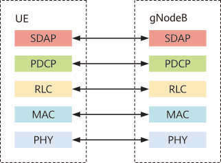
At the beginning of 5G system design, each protocol layer on the user plane was optimized for URLLC.

Low-latency technologies are mainly applied at the physical layer, MAC layer, and RLC/PDCP layer. table below describes related technologies to reduce latencies.
|
User-Plane Protocol Layer |
Technology |
|---|---|
|
Physical layer |
Self-contained slot |
|
Scalable numerology |
|
|
Channel coding with better performance |
|
|
MAC layer |
Uplink grant-free scheduling |
|
Downlink preemption scheduling |
|
|
Asynchronous HARQ |
|
|
HARQ enhancement |
|
|
RLC/PDCP layer |
PDCP out-of-order delivery |
Benefit from Massive discount on our 5G Training with 5WorldPro.com
Start your 5G journey and obtain 5G certification
contact us: contact@5GWorldPro.com


