Introduction: When Antennas Break the Rules
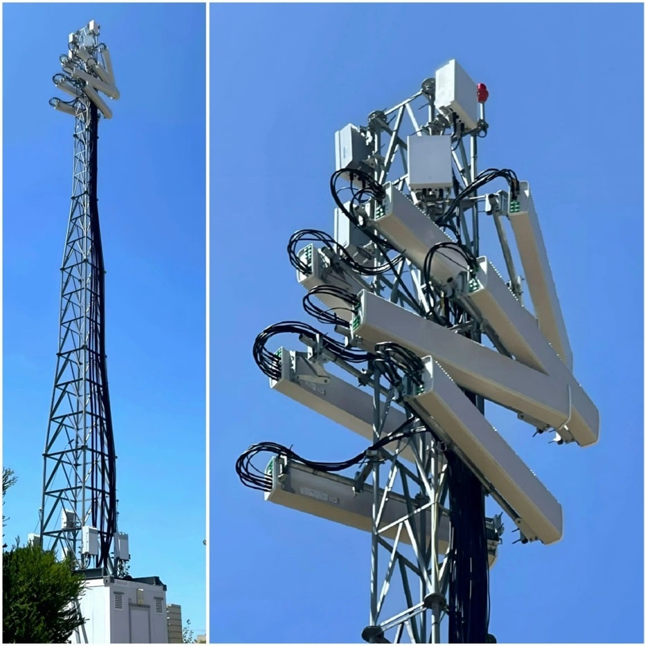
If you have ever walked past a cell tower and noticed panel antennas mounted horizontally instead of vertically, your first reaction was probably the same as mine: something went wrong during installation. But have you ever wondered, why are these 5G antennas mounted sideways?
But what if I told you it was done on purpose?
This unconventional antenna configuration has sparked heated debates among RF engineers worldwide. When I shared a photo of this exact setup on LinkedIn, it generated nearly 1,000 reactions and 148 comments from senior RAN engineers, antenna company founders, and field deployment specialists across four continents.
The insights that emerged reveal a fascinating lesson about the gap between textbook antenna theory and real-world network engineering — a gap that every aspiring 5G professional needs to understand.
In this article, we will break down exactly why operators rotate panel antennas, when it makes sense, the trade-offs involved, and what this teaches us about practical 5G RAN deployment.
1. How a Standard Panel Antenna Works
Before understanding why someone would rotate an antenna, you need to understand how a standard sector antenna radiates.
A typical macro cell panel antenna is designed for vertical mounting. In this default orientation, it produces a radiation pattern with two key characteristics:
| Parameter | Horizontal (H-Plane) | Vertical (V-Plane) |
|---|---|---|
| Beamwidth | ~65° | ~7–10° |
| Purpose | Covers a wide sector | Focused, narrow coverage |
| What it means | Broad coverage across the azimuth | Tight beam directed toward the ground |
This design is optimized for the most common deployment scenario: a tower serving users spread across a wide area at ground level. The wide horizontal beam covers the full sector (typically 120° with three sectors per site), while the narrow vertical beam directs energy downward toward users and minimizes interference to neighboring cells.
2. What Happens When You Rotate a Panel Antenna 90°?
When a standard panel antenna is rotated 90 degrees from vertical to horizontal, the beamwidth values swap:
| Plane | Standard (Vertical Mount) | Rotated (Horizontal Mount) |
|---|---|---|
| Horizontal Beamwidth | ~65° (wide) | ~7–10° (narrow) |
| Vertical Beamwidth | ~7–10° (narrow) | ~65° (wide) |
This single physical change completely transforms the antenna’s radiation behavior. Instead of covering a wide azimuth sector with a narrow vertical beam, you now have a narrow horizontal beam with wide vertical coverage.
This is not a theoretical exercise. Real operators have deployed this configuration in production networks — and for very specific reasons.
3. Three Real-World Use Cases for Rotated Antennas
Use Case 1: High-Rise Building Coverage
In dense urban environments, users may be distributed vertically across 30 or more floors within a single high-rise building. A standard vertically mounted antenna, with its narrow 7–10° vertical beamwidth, can only effectively serve a few floors at a time.
By rotating the antenna, the wide vertical beamwidth (now 65°) illuminates all floors simultaneously, while the narrow horizontal beamwidth (7–10°) targets only the building of interest, reducing interference to surrounding cells.
Real-world example: An RF engineer reported deploying this configuration in Mumbai, India, at a hotel podium to serve indoor coverage for a high-rise building where a traditional DAS (Distributed Antenna System) was not feasible.
Use Case 2: Capacity Boosting at High-Density Events
Before the advent of multibeam and pentabeam antennas, operators needed creative solutions to increase sector capacity at large outdoor events such as music festivals, stadiums, and conventions.
By rotating standard panels, operators could split one wide 65° sector into multiple narrow 7–10° sectors within the same azimuth range. This effectively multiplied the number of sectors serving the same area, dramatically increasing capacity without deploying additional expensive specialized antennas.
Real-world example: A 5G NR/LTE RNO Engineer and Co-Founder at a Portuguese telecom company confirmed that operators in Portugal have been using this technique at music festivals since 2017. After more than 7 years of continuous use, the configuration is still active — strong evidence that it delivers real results in the field.
Use Case 3: Inter-Cell Interference Reduction
In some dense urban deployments, the primary challenge is not coverage but interference. A narrow horizontal beam limits energy spillover into neighboring cells, reducing inter-cell interference without requiring additional hardware investment.
A Senior RAN Expert at a major operator confirmed that this type of installation can reduce interference in the horizontal direction while improving coverage for high buildings — validating it as a deliberate RF engineering choice rather than an installation error.
4. The Trade-Offs: Why This Is Not Standard Practice
If rotating antennas is so useful, why is it not done everywhere? Because the trade-offs are significant:
| Trade-Off | Impact |
|---|---|
| Cross-Polarization Degradation | The antenna’s designed cross-pol discrimination (XPD) is optimized for vertical mounting. Rotating it degrades MIMO performance and polarization diversity. |
| PIM Risk | Passive Intermodulation risk increases due to non-standard mechanical stresses on connectors and mounting hardware. |
| Radio Planning Limitations | Standard RF planning tools (Atoll, ASSET, Planet) do not natively model rotated antenna patterns. Engineers must manually import custom patterns. |
| Wind Load & Mechanical Stress | Horizontal mounting changes the wind loading profile. The antenna and mounting bracket experience forces they were not originally designed for. |
| No Vendor Support | This is not a commercially supported configuration. Antenna manufacturers do not guarantee performance specifications when mounted outside designed orientation. |
| Electrical Tilt Ineffectiveness | Remote Electrical Tilt (RET) adjusts the vertical beam pattern. When rotated 90°, electrical tilt now acts on the horizontal plane, making standard tilt optimization tools ineffective. |
5. What Does This Mean for Modern 5G Deployments?
The transition to 5G NR and Massive MIMO has made many of these creative workarounds unnecessary. Here is how modern technology addresses each of the use cases above:
| Legacy Approach | 5G NR Solution | Key Technology |
|---|---|---|
| Rotated panel for high-rise | Massive MIMO vertical beamforming | 3D beamforming with 64T64R or 32T32R AAU |
| Rotated panel for capacity | Multi-beam antennas & dynamic sectorization | Pentabeam antennas, SSB beam sweeping |
| Rotated panel for interference | Advanced interference management | SRS-based scheduling, MU-MIMO, coordinated beamforming |
However, in markets where 5G deployment is still in its early stages, or where legacy 4G infrastructure dominates, understanding these field techniques remains highly relevant. Many operators in Africa, South Asia, and parts of Latin America continue to deploy 4G macro networks where creative antenna solutions can make a real difference in coverage and capacity.
6. Key Takeaways for RF Engineers and 5G Professionals
- Antenna beamwidth is defined by the physical aperture. Rotating the antenna physically swaps the H-plane and V-plane beamwidths.
- A standard 65° / 7–10° panel becomes a 7–10° / 65° antenna when mounted horizontally — creating a narrow horizontal beam with wide vertical coverage.
- Real-world use cases include high-rise coverage, temporary capacity boosting at events, and inter-cell interference reduction.
- Trade-offs are significant: cross-polarization degradation, PIM risk, radio planning tool limitations, mechanical stress changes, and loss of electrical tilt functionality.
- Modern 5G NR technologies (Massive MIMO, 3D beamforming, multi-beam antennas) provide superior solutions, but understanding the legacy approach builds critical RF intuition.
- The best RF engineers combine textbook theory with field experience. Classroom knowledge alone does not prepare you for real-world deployment challenges.
7. Build Your 5G Expertise with Hands-On Training
Understanding real-world deployment scenarios like rotated antenna configurations is exactly what separates a certified 5G professional from someone who only knows the theory.
At 5GWorldPro.com, our training programs are built by industry practitioners who have designed, deployed, and optimized real mobile networks — not by academics working from textbooks.
📡 EXPLORE OUR 5G TRAINING CATALOG
Master 5G RAN, Open RAN, FRMCS, Private Networks, NTN & more
Courses designed by network engineers, for network engineers
Recommended Courses Related to This Article:
- 5G RAN Architecture & Deployment — Covers antenna systems, beamforming, Massive MIMO, and real-world RF planning
- 5G FRMCS Training (7 Modules, 6 Hours) — Railway communications including antenna design for high-speed mobility scenarios
- Open RAN Architecture & Deployment — Understanding disaggregated RAN and its impact on antenna and radio unit design
- 5G Private Networks — Indoor and outdoor antenna strategies for enterprise deployments
Conclusion
The sideways antenna is a reminder that telecommunications is as much an art as it is a science. The best RF engineers are not the ones who memorize 3GPP specifications — they are the ones who understand why a field team in Portugal chose to rotate a panel antenna at a music festival, and whether that same approach could solve a coverage problem in Mumbai, Casablanca, or São Paulo.
If you found this article valuable, share it with your network. And if you want to develop the kind of practical 5G expertise that goes beyond textbooks, explore our training catalog at 5GWorldPro.com.
Benefit from Massive discount on our 5G Training with 5WorldPro.com
Start your 5G journey and obtain 5G certification
contact us: contact@5GWorldPro.com
